Raspberry Pi live video streaming Bird Box
Contents
Introduction
This year (2016) I thought I would install a bird box in our back garden, I have a shed at the end of the garden and the gable end which faces the house is North facing, which apparently is a good direction for a bird box (in the northern hemisphere anyway).
I thought it would be interesting to put a Raspberry Pi camera in it, so I did, along with a couple of temperature modules. It is generally based on this guide by the Raspberry Pi Foundation, but I have enhanced it significantly by using picamera.
There is potential for cramming in lots of Raspberry Pi learning experiences into this project. So I thought I would document the project here.
- How to stream video from the Raspberry Pi camera to the internet
- Using Raspivid initially
- Later using picamera to allow further enhancements
- Getting an internet connection to a remote shed
- Using IR LED’s (Infra Red Light Emitting Diodes)
- Adding sensors to record temperature
- Logging temperature and creating a nice chart
- Tweeting pictures from the bird box automatically
- Adding overlay text with sensor and time data to the pictures
- Setting up motion detection so a tweet can be sent when motion is detected with a link to the live stream.
There is a lot to do, but all projects are best broken down into smaller steps. I have made progress with the top half of this list, but since birds are very seasonal animals I thought I should concentrate on getting the bird box installed, after all, the software can be worked on, tweaked and updated once the box is installed.
This page is work in progress, I shall be completing it shortly.
Documentation
Build instructions
So what will you need. Here is a list of the components I used.
Equipment
Required
- Birdbox, I used one almost identical to the one suggested by the Raspberry Pi Foundation from here
- Raspberry Pi infra red camera, or the Pi NoIR as it is called.
- An extra long ribbon cable for the Pi camera.
- 5mm IR LED’s
- Equipment wire
Optional
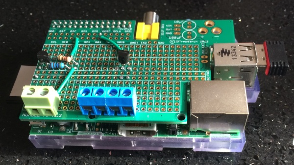
- Prototyping board, I used a HumblePi which is suitable for a model B Pi, similar are avaialble for the A+ and B+ and Pi2 such as this
- I designed a 3D printable mount for the camera and IR LED, files can be downloaded from here
- LED mounts, such as these to fit the LED in to the mount
- Temperature sensors, I used two DS18B20’s, one sealed probe type and another in TO92 package
- I also needed a few screw fixings, a Chinese takeaway box and some flexible plastic conduit.
Here I will take you though the process I went through to assemble all the components into the bird box.
Location
The location I had chosen was on the North face of the shed at the end of my garden (I will talk about getting internet connectivity to this in the software section). I am no wild life expert so if you feel I suggest something that is not correct please let me know. But I had heard that the bird box should not be placed looking South, exposed to the mid day sun (in a Northern hemisphere country) since the box will get too hot inside during the summer.
I planned to fix the bird box to the outside of the shed and route the camera ribbon cable and the wires for the external temperature sensor and IR LED into the shed where I would mount the Raspberry Pi. I had power in the shed so I would use this to power the Pi.
Bird Box
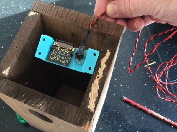
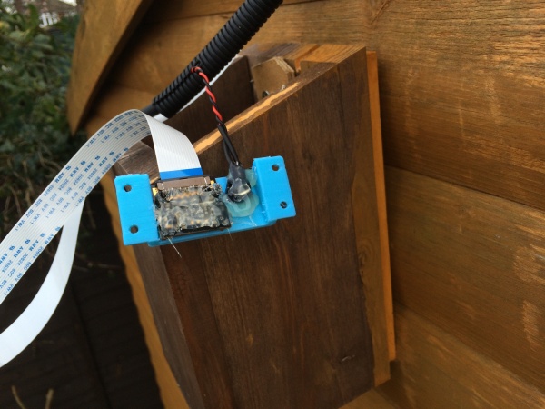
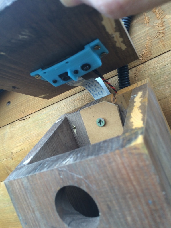
First up I had a good look at the bird box, the top unscrewed easily gaining access to the inside. The plan was to mount the camera on the underside of the roof so it looked directly downwards. The Raspberry Pi guide was very good, but I did not like the idea of the camera being held in place with tape, after all, what would happen if birds moved in and the camera or IR LED fell down, I would not be able to get in and fix it. So I designed a 3D printed mount for the camera and IR LED, it can be downloaded from here.
Camera
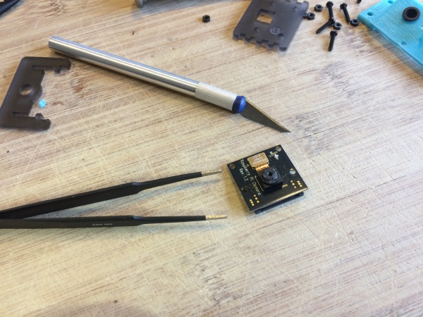
The Pi cameras both the regular and the IR version come with a fixed focus lens, but fortunately they are only fixed by three small pieces of glue, once removed the lens can be rotated to focus, this is necessary in this case since the bottom of the bird box is relatively close, so it is necessary to focus.
I removed the three blobs of glue with a sharp knife.
I was not looking forward to this but it was easier than I thought it would be. Prod the glue a few times and then try and turn the lens with a pair of tweezers, if it does not turn then prod a bit more with the knife and repeat. It only took a couple of minutes. The lens will need to be rotated counter clockwise, but I did this later.
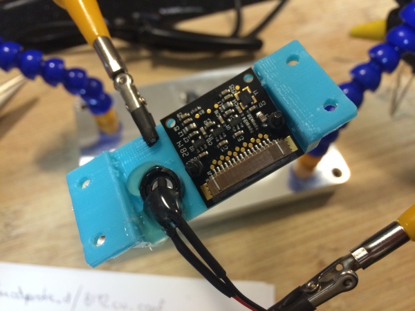
I securely fixed the camera to the 3D printed mount, using the fixings that came with the Pimoroni camera mount kit.
IR LED
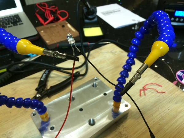
I cut two lengths of 2m long equipment/hook up cable, I used red and black and stripped one end of both lengths. Threaded on some heat shrink tubing of the wire and tinned the bare ends of the wire. Next I cut the leads of the IR LED down to about 10mm long each, take care you make a note which of the leads is the anode and cathode, a marker pen can be handy for this.
I then soldered the red wire to the anode and the black wire to the cathode, slide the head shrink tubing over the bare joint and shrunk the tubing with the heat from a match or two.
To fit the LED into the 3D printed mount I used a cheap plastic mount. First place the holder into the mount from the face that will point to the bottom of the bird box, then slide the retaining ring over the LED and slide the LED into the back of the retainer, it should click into place. The retaining ring can then be pushed over the back of the LED and retainer holding the LED securely in place. The wires coming off the LED can then be folded over 90 degrees so that the wires can exit the back of the bird box.
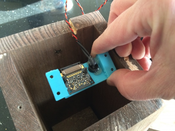
The mount with camera and LED can now be fixed to the lid of the bird box with small wood screws. Make sure the camera lens is centered, since it is not central in the mount.
To power the LED is should be connected to 5v through a 220 ohm resistor. Once this is connected to the Raspberry Pi it will be on full power as long as the Pi is on, the brightness cannot be altered and it cannot be turned off. To get over this I decided to power the LED through a transistor which could then be controlled safely with a GPIO port. You can skip this part if you want, but I wanted a bit of control, since once it was installed I did not want to be messing about with it again, especially if birds move in.
Setting the camera focus
To ensure the camera is properly focused the camera needs to be connected up to the Raspberry Pi and the video camera fired up.
The camera comes with a fairly short ribbon cable, now is probably the time to fix the longer one. To remove the existing cable carefully prise open the black retaining clip, use a small plastic spudger or similar, working both sides gently until it is fully open and loose. the original cable can then simple be pulled out. Replace with the new longer ribbon cable, the important thing is to make sure you get the metal connections facing the correct way. On the camera module they should face towards the PCB. Make sure it is fully inserted and square. Only a small amount of the metal connectors should be seen when fully inserted. Whilst holding the cable in position, carefully squeeze the retaining clip back into position making sure both sides are fully engaged. When complete check the cable is still fully inserted and square, gently give the cable a pull to make sure it does not come free.
Do the same thing on the Raspberry Pi, the metal connectors should face away from the USB/Ethernet ports.
I then plugged the Raspberry Pi into a monitor, turned it on and logged in. To check the focus I used the raspistill command line tool to run the video camera in preview mode such that the focus could be checked. The command was
raspistill -p -t
Run this command to check the focus, remember when a bird is in the box it will be on some bedding, so you probably want to put something inside the box to focus on, rather than focusing on the base. Keep adjusting the focus ring and running the above command until you are happy the image is in focus.
Connecting it all up
The wires from the IR LED and the ribbon cable have to exit the box, the ribbon cable will not be a problem, but the IR LED wires would need a small slot, so next I lines up the camera mount and marked and then cut a small slot.
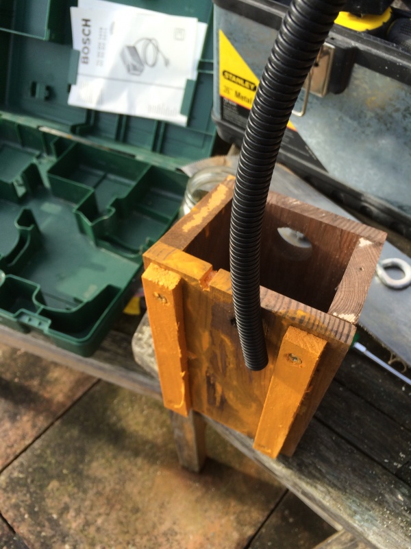
I then mounted a couple of battens to the back of the box, this would be so it fitted flush to the side of the shed and would also provide somewhere for the temperature probe to live.
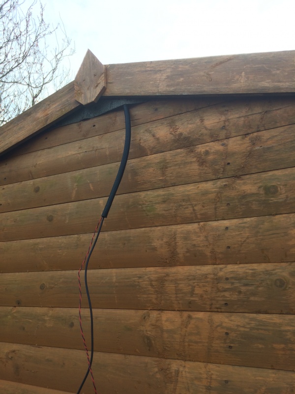
I then found some flexible plastic duct and routed it into the shed, through this I pushed the wires from the temperature probe and the IR LED
I then screwed the box to the shed and started putting everything into position, before screwing the camera to the roof I covered the camera module in hot glue, in the hope this will give it some corrosion protection.
I then fixed the camera into position on the roof, laid all the cables out nicely and screwed the lid shut.
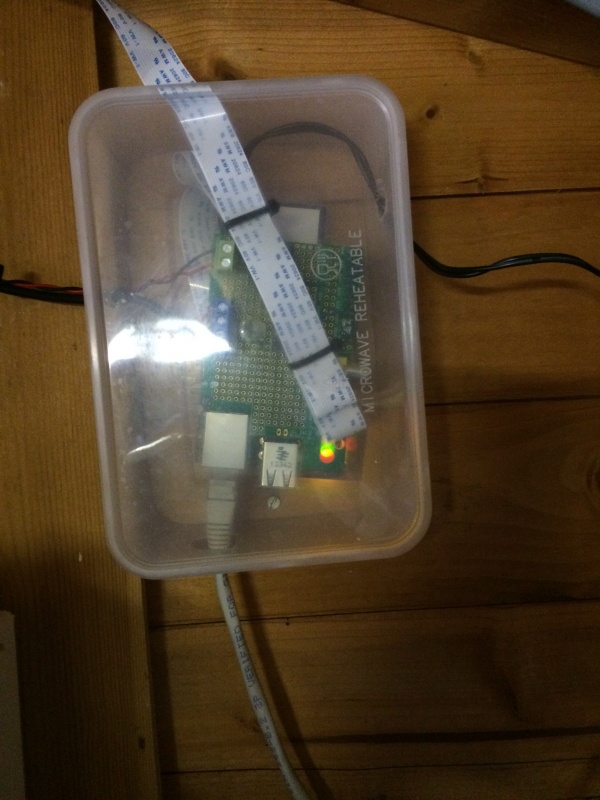
Next up, I routed the cables into the shed, fixed a Chinese takeaway box to the shed connected the wires up to the Pi and put it in the box and put the lid on.
So that’s the hardware sorted, next up I'll show how I connected up the IR LED, transistor and the temperature sensors.
Guide to electronics setup
Software guides
Infra-red LED=
Logging data to ThingSpeak
Streaming video to uStream
using raspivid
using picamera
with live text overlay
Adding live temperature data to the text overlay
to follow
Also in the pipe line, streaming to YouTube, plus hopefully motion detection with tweeting
Watch here
I am using the free ustream service so you may get an advert before the live stream, just sit it out, the stream will appear. Live Video Stream
Temperature Monitoring
Live external and internal temperature plots can be seen here. The external sensor is behind the bird box exposed to the air. The internal sensor is on the Raspberry Pi interface board and is enclosed inside a box with the Raspberry Pi which is inside a shed.
