Difference between revisions of "Soldering Tutorial"
(→The kit) |
m (1 revision imported) |
(No difference)
| |
Latest revision as of 20:14, 6 June 2017
Contents
Introduction
On 24th September 2015 Keith Ellis presented a hands-on soldering tutorial at the Ipswich Makerspace. The contents of which are included below.
Keith Ellis is not a professional solderer, he learned the basics at school during GCSE electronics and gained further experience over the years practicing as a hobby. This guide is therefore based on Keith's experience, it works for him but is by no means the only way to solder, ultimately you should do what works for you.
What do we need
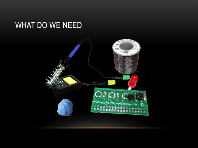
So the essentials are:
- Soldering iron, any will do, as long as it gets hot and the tip is in reasonable condition. Soldering is possible with most irons if you have the right technique. So use what is available. as you get more experience you may want to upgrade, but don't feel you have to.
- Solder, everyone has an opinion about the pros and cons of leaded or lead free, I've used both and can solder with both. Again, use what you can get your hands on.
- Some components and a PCB to solder, could be strip board or prototype board.
- Blu-tack - useful for holding components in place as you solder, as well as holding the PCB to your work bench.
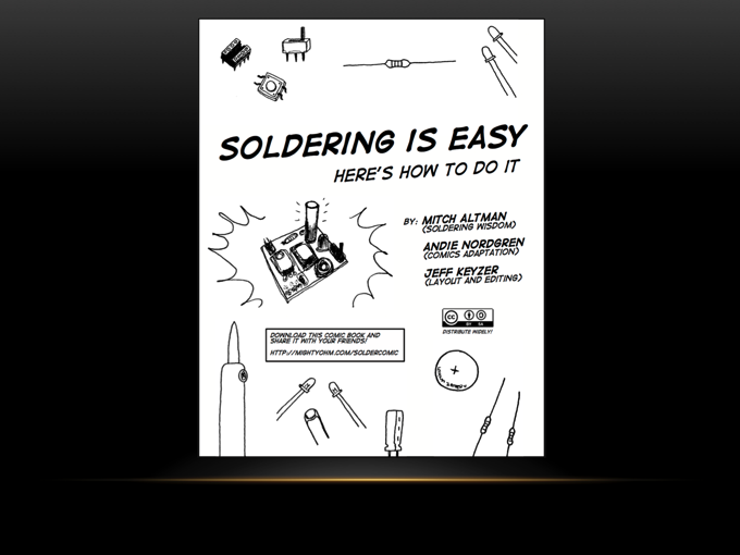
Soldering is easy
A great resource is the Solder Comic written by Mitch Altman, Andie Nordgren and Jeff Keyzer. They have released it under the CC-BY-SA license so Keith has borrowed a few pages and used it in this guide.
You can get the complete guide here http://mightyohm.com/soldercomic
Safety First
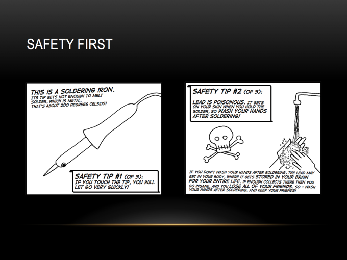
Warning, the pointy end of the soldering iron gets hot, very hot. But also, the components also get hot, just be aware of what has been heated up and be cautious. Burns hurt.
In addition, solder, particularly leaded solde is harmful. Lead is easily absorbed into the body but the body is unable to get rid of it, so can build up over a period of time. Ensure you wash your hands well after soldering and before eating or smoking.
Components
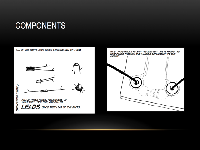
The point of soldering is to electrically connect various components together, via the tracks on a PCB with solder. This tutorial is concerned with 'through hole soldering', this is where the various components have leads which pass though the PCB and the solder is applied to the PCB pads on the reverse side to which the components are placed.
Always follow any instructions which come with the PCB, some components including LED's and some capacitors must be placed a particular way round, i.e. they have polarity, with one lead being positive and the other negative. Resistors do not have any polarity and can be placed either way round. Integrated Circuits, IC's or chips must also be placed in a particular orientation. Pin one on the IC and on the board are usually identified which should be aligned.
Lets solder
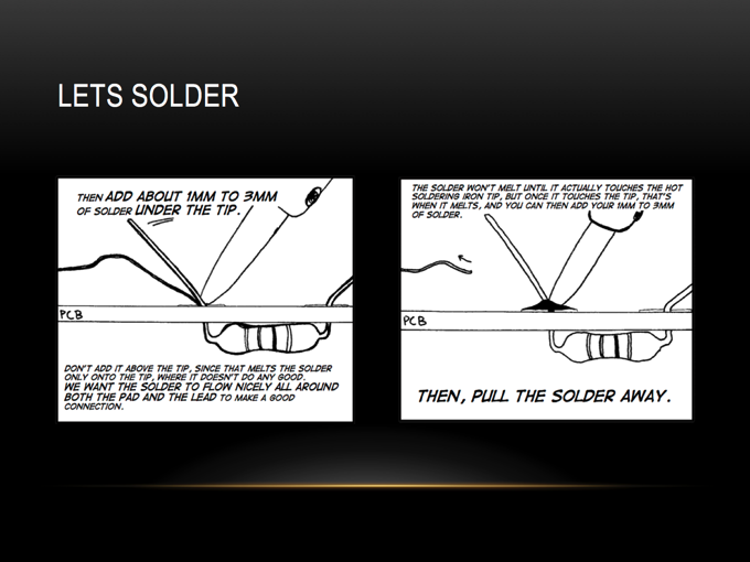
The key point to remember about solder is that solder flows to heat. Therefore if we want a good solder joint both the pad on the PCB and the lead on the component must both be hot. A common mistake can be to place the iron tip onto the board, then push the solder into the iron tip to melt a blob of solder onto the board. The problem with this is that if the pad of the lead are not hot, the solder may not make a good connection. Known as a dry joint.
Keith has found the best way to get a good connection is as follows:
- Place the iron tip such that it touches both the PCB pad and the component lead, a small amount of solder on the iron tip before hand is a good idea to help conduct heat.
- The solder should then be pushed against the pad and the lead on the opposite side to the iron. If the solder does not melt, don't be tempted to touch the solder to the iron tip, wait another second or so and try again.
- When the pad and lead are hot enough the solder will easily melt and flow easily in and around the joint.
- Once enough solder has been applied always remove the solder first, leave the iron in place for another second or so to allow the solder to fully flow into position, then remove the iron.
- inspect the joint, the solder should have flowed fully around the component lead covering the pad, solder should also be visible on the reverse side of the board through the lead hole.
The kit
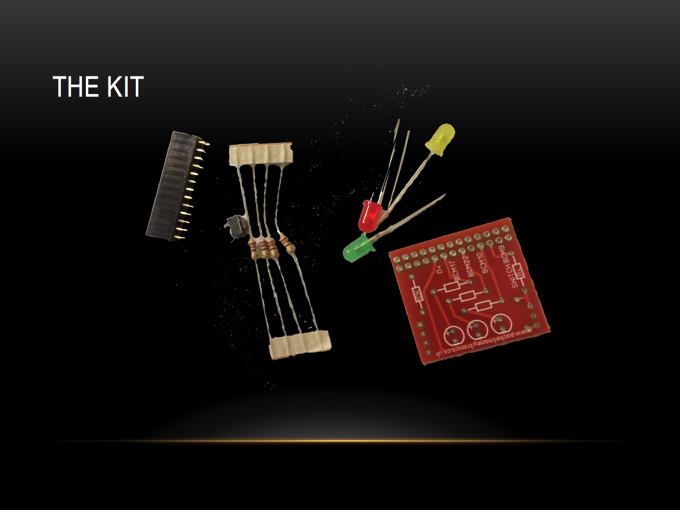
In this tutorial we used the basic Raspberry Pi add on kit by http://www.pocketmoneytronics.co.uk. It consists of a small printed circuit board (PCB), a 26 way header, used to connect the board to a Raspberry Pi, three light emitting diodes (LED's) a switch and four resistors.
More information
Some good references are to review are as follows:
- http://mightyohm.com/soldercomic - Link to the Mighty Ohm Soldering Comic
- http://bit.ly/soldering-howto - A short video by Keith Ellis demonstrating some of the techniques referenced above
- http://bit.ly/EEVBlog-soldering - A playlist on the EEVBlog YouTube channel with some soldering tutorials
- http://wiki.ipswichmakerspace.com/index.php?title=Soldering_Tutorial - This page
- http://www.pocketmoneytronics.co.uk/?page_id=125 - Info and demo Python scripts for the board used in the practical.
